
A Thorough Examination of Circuit Breaker Health
Article from Electric Energy T&D, Magazine – May-June 2006 Issue
Preface
This article is the first in a series of articles that will help to bring light to the maintenance practices presently applied to power circuit breakers.
A list of the most popular tests used; with reference to the international standards compliance, is included at the end. Each test provides a bit of information that is complementary to the others, providing a general overview of the circuit breakers testing practices.
A circuit breaker is an important equipment to power electric networks. Its importance is due to the protection role it is playing. Hence, it is imperative to assure its proper operation. This is only possible by applying suitable maintenance.
The main purpose is to help us understand, accurately, the real condition of the breaker being tested thus helping targeting the corrective actions. This targeting helps minimize maintenance spending and increase network reliability, hence leading to efficient network management.
Introduction
A power circuit breaker is equipment intended to switch on and off electric currents on power transmission and distribution networks for routine operations and protection of other equipment.
Electric transmission system breakups and equipment destruction can occur if a circuit breaker fails to operate because of a lack of preventive maintenance.
Description
 Its name, circuit breaker, indicates clearly its role. It breaks electric circuits. To achieve this purpose, it separates mechanically two points in the circuit to a certain distance large enough to break the flow of electric currents.
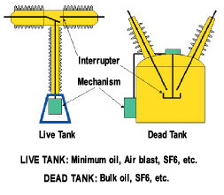
Circuit breakers come in a great variety and use different technologies:
Despite the big difference all types share common principals, they all have to provide two main functionalities highly related:
– Electrical functionality (Interrupter).
– Mechanical functionality (Mechanism).
Electrical functionality
Circuit breakers are designed to satisfy predetermined breaking conditions and have electrical properties that can be resumed by the following:
– Current carrying property;
– Insulating property;
– Current breaking property.
Mechanical functionality
 The requested electrical properties imposes mechanical properties that can be more or less demanding depending on the used technology:
Current carrying property imposes:
- Contact material that is highly conductive;
- High quality of contact make;
- Low contact reaction to ambient atmosphere and temperature.
Insulating property, depending on the voltage level imposes:
- The contacts parting distance in open position;
- Line to ground distance;
- Characteristics of the insulating medium and reaction over time.
Current breaking & making properties, imposes:
- The speed of the opening or closing contacts;
- Arc blowing techniques;
- Resistant to arc material;
- Energy required to carry on the breaking or making of large short circuit currents;
- Characteristics of the insulating medium and reaction over time and frequency of current interruption.
Frequency of operation property influences greatly all the above-mentioned parameters.
Preventive maintenance
The need for maintenance of circuit breakers is often not obvious, as circuit breakers may remain idle, either open or closed, for long periods of time. The need to predict the proper function of circuit breakers grew over the years as transmission networks expanded and carried increasing energy to longer distances.
The technology advance over the years brought low maintenance breakers but it did not bring more reassurance to network management as to the reliability of operation.
The circuit breaker is, in fact, a black box. The only way to be sure of its condition is to open it for physical inspection. Unfortunately, this way is costly and must be reduced to minimum to prevent unnecessarily maintenance.
Predictive maintenance
Maintenance people created what is now widely known as the predictive maintenance. The purpose is to predict accurately the condition of the breaker, without having to open it for inspection.
Required open inspection would then be limited to corrective or preventive intervention, thus reducing dramatically the cost of maintenance and increasing to the same level its efficiency.
The prediction can take three ways complementary to each other:
TESTING: a wide range of tests where invented to verify the conformity of each of the electrical and mechanical properties to meet the design criteria. Some of these tests are acknowledged and documented by international standards (IEC, ASTM, etc.). Some are still under development and promise great expectations.
MONITORING: continuous surveillance of the breaker by the means of multitude transducers controlled by a computer. Alarms or actions are triggered when settings are reached thus permitting just in time intervention. This way is still under development and is very promising.
STATISTIC STUDY: continuous measurements, samplings and maintenance interventions, are noted over the years on each breaker. This information assembled in databases, helps conduct statistic studies aiming to target the faulty components or helps a probabilistic modeling of aging in Circuit Breakers for Maintenance.
A practice widely spreading by network administrators, is to require for each type of new breaker a statistic study from the supplier on the reliability of the new equipment components, based on their own experience. This will help to focus the maintenance actions on the most vulnerable parts.
Safety Practices
Maintenance procedures have to respect the safety practices and the following points require special attention:
a) Be sure the circuit breaker and its mechanism are disconnected from all electric power, both high voltage and control voltage, before it is inspected or repaired.
b) Exhaust the pressure from air receiver of any compressed air circuit breaker before it is inspected or repaired.
c) After the circuit breaker has been disconnected from the electrical power, attach the grounding leads properly before touching any of the circuit breaker parts.
d) Do not lay tools down on the equipment while working on it as they may be forgotten when the equipment is placed back in service.
Breaker testing
Maintenance tests enable personnel to determine if breakers are able to perform their basic circuit protective functions.
The tests mentioned in the following table of tests, may be performed during routine maintenance and are aimed at assuring that the breakers are functionally operable. These tests are to be made only on breakers and equipment that are deenergized.
The Table of Tests lists the tests and their purposes, regrouped by the purpose category (Mechanical, Electrical, Chemical).

In general, to conduct a successful test, the following conditions has to be observed:
- Application procedure (provided by the test equipment provider);
- Design specifications with defined tolerances (provided by the breaker designer);
- The breaker instruction book and related outline, basic and elementary drawings (provided by the breaker designer);
- The international standards definitions and specifications if required by the test.
- Good sense of analysis
Maintenance Program
The same need to predict the proper function of circuit breakers that created the predictive maintenance, and since it is not feasible to test indefinitely the circuit breakers, it was obvious to structure the maintenance acts in a maintenance program that defines the maintenance actions and frequency.
Most of breaker manufacturers recommend maintenance programs that suit better their equipment. They generally define three levels:
1 – Routine inspection: includes:
- Visual inspection of the outer shape of the equipment.
- Checking the operation counters.
- Checking the pressure gauges.
- Detecting visual or audible leaks.
- Measuring temperature.
- etc.
This is done with the breaker in service.
Frequency: generally 6 months to 1 year
2 – Minor maintenance: Includes, in addition to the routine inspection:
- Thorough inspection of the state and function of subassemblies,
- Breaker testing
- Minor interventions to replace easy access ware parts,
- Changing filters, oil or gas etc.
This needs to isolate the breaker from the network.
Frequency: generally 6 to 8 years
3 – Major maintenance: Includes, in addition to the minor maintenance, opening the major assemblies to access internal parts:
- Interrupter;
- Mechanism;
- Tank receiver.
This needs to isolate the breaker from the network.
Frequency: depends on breakers technology (12 years for air blast, 20 years for SF6, etc.)
Bibliography
MAINTENANCE OF POWER CIRCUIT BREAKERS; HYDROELECTRIC RESEARCH AND TECHNICAL SERVICES GROUP; FACILITIES INSTRUCTIONS, STANDARDS AND TECHNIQUES VOLUME 3-16; UNITED STATES DEPARTMENT OF THE INTERIOR BUREAU OF RECLAMATION DENVER, COLORADO.
About the Authors
El Dr. Fouad Brikci is the president of Zensol Automation Inc. He was the first to introduce the concept of truly-computerized test equipment in the field of circuit breaker analyzers. As a former university teacher in Ecole Polytechnique – Algiers and CNRS LAAS researcher in France, Dr. Brikci has developed experience in the fields of electronics, automation, and computer science. Most activities were focused on the industrial application of computers. Among his achievements are the development of fully computerized measuring systems for quality control in circuit breaker manufacturing, laboratories, and maintenance services of electric utilities. Dr. Brikci holds a PhD in Electronics and a Master in Sciences in EEA (electronics, electrotechnics, and automation) from the University of Bordeaux, France.
Emile Nasrallah is an electrical engineer specialized in Power circuit breakers maintenance. Since graduation in 1984 he worked as a field engineer. In1990 he joined the worldwide circuit breaker manufacturer GEC ALSTHOM as a specialized field engineer. In 1997 he became the manager of MV & HV circuit breaker SF6 division of ALSTOM, responsible of technical support, maintenance and training for SF6 circuit breakers. In 2001 he became manager of Air blast circuit breaker division for AREVA. He was in charge of the Air blast (PK and PKV) refurbishing program in partnership with hydro-Quebec and introduced a unique administration system for the program (average of 35, 735 kV PK air blast circuit breaker per year). In 2005 he joined General Electric Company of Canada as a senior circuit breaker specialist and is in charge of the circuit breaker division of the Montreal service centre, responsible of the remanufacturing program for Oil circuit breakers.